


Views: 0 Author: Site Editor Publish Time: 2026-06-17 Origin: Site


Screw centrifugal pumps routinely tackle the harshest industrial fluid applications. We deploy them for highly demanding, solids-laden, or shear-sensitive fluids. Standard centrifugal units often stall or fail under these extreme conditions. In these aggressive environments, mechanical seal failure represents the primary cause of unplanned downtime.
Evaluating whether a standard seal suffices or if you require an active cooling flush system is a critical engineering decision. Over-specifying creates unnecessary system complexity and wastes resources. Under-specifying inevitably invites catastrophic fluid leakage and environmental hazards.
This guide provides an objective, engineering-focused breakdown of mechanical seal structures. We will analyze how they function inside robust pump architectures. We will also establish a clear decision matrix for when cooling systems become strictly mandatory. Read on to master seal configurations and safeguard your industrial operations.
The screw centrifugal pump bearing housing dictates shaft stability; robust housing design directly minimizes shaft deflection, which is the baseline requirement for mechanical seal longevity.
Mechanical seal structures for this pump type generally fall into Single (for mild/moderate fluids) or Double/Cartridge configurations (for hazardous, abrasive, or high-temp fluids).
Cooling is not universally required but becomes mandatory based on three distinct thresholds: fluid temperature exceeding elastomer limits (typically >80°C/175°F), the presence of crystallizing/abrasive solids, or high-friction low-lubricity fluids.
Selecting the right API seal support plan (e.g., Plan 53A, Plan 54) requires balancing upfront installation costs against the long-term risk of environmental non-compliance and pump failure.
Screw centrifugal impellers feature a unique corkscrew geometry. This design pulls thick, viscous media smoothly without shearing the fluid. However, this pumping action generates distinct radial and axial loads. The pump shaft experiences intense, dynamic bending forces during operation. These loads fluctuate wildly when handling irregular solids or sludge.
Shaft deflection is the enemy of any mechanical seal. A heavy-duty Bearing Housing Pump design actively absorbs these unpredictable loads. It anchors the rotating assembly firmly in place. This rigid support keeps shaft deflection at the seal faces strictly within industry tolerances. Engineers typically limit this deflection to under 0.05mm. If the shaft bends beyond this limit, the mating faces open. Abrasive particles immediately enter the gap and destroy the lapped surfaces.
Beyond load absorption, the housing performs a vital physical isolation function. It securely separates the wet end from the dry drive end. The wet end houses the pump casing and the rotating impeller. The drive end contains the motor components. The housing provides a dedicated physical cavity between them. This chamber delivers the precise environmental control necessary for the mechanical seal to function. It acts as a protective bunker against volatile process fluids.
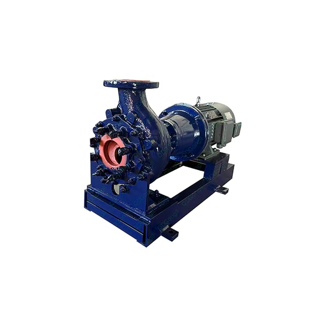
Industrial operations demand specific seal structures based on fluid aggression. We generally categorize these structures into single and double configurations. Each offers distinct operational advantages.
A single mechanical seal contains exactly one set of mating faces. One face remains stationary while the other rotates with the shaft. A spring mechanism presses them together.
These seals perform best in applications handling mild fluids. They work well for fluids providing their own lubrication. You can deploy them safely for liquids exhibiting low toxicity and moderate temperatures.
However, single seals possess a critical limitation. They offer zero redundancy. If the mating faces fail, process fluid immediately breaches the atmosphere. It will inevitably flood the surrounding environment and potentially damage the motor.
Double seals feature two complete sets of mating faces. Manufacturers arrange them in back-to-back, face-to-face, or tandem orientations. They require a dedicated barrier or buffer fluid injected between the two seals. This fluid stabilizes the environment.
These dual structures are strictly mandatory for aggressive media. They dominate applications moving abrasive, toxic, or high-solids fluids. You will frequently find them inside a Screw Centrifugal Pump Bearing Housing processing wastewater sludge or paper stock. The inner seal contains the harsh product. The outer seal contains the clean barrier fluid.
Modern facilities increasingly rely on cartridge mechanical seals as the baseline standard. These units combine the faces, springs, and gland plate into one pre-assembled package. Cartridge seals arrive with pre-set spring tension. This design eliminates manual measuring during installation. It significantly reduces human error during routine maintenance.
Table 1: Mechanical Seal Configuration Comparison | |||
Configuration | Primary Application | Redundancy Level | Installation Complexity |
|---|---|---|---|
Single Component Seal | Clean water, lubricious liquids | None | High (Requires precise setting) |
Double Component Seal | Toxic or abrasive fluids | High | Very High (Complex alignment) |
Double Cartridge Seal | Harsh sludge, paper stock | High | Low (Pre-set assembly) |
Many operators mistakenly assume every mechanical seal requires an external cooling loop. In reality, cooling is strictly application-dependent. Rotating seal faces constantly generate severe friction heat. You must dissipate this heat efficiently. If heat builds up, the liquid film vaporizes. Face distortion occurs rapidly. Elastomers will degrade and melt.
You can operate safely without active cooling in specific scenarios.
Pumping cool, relatively clean water.
Handling highly lubricious fluids at low operating pressures.
Utilizing a simple bypass flush system (API Plan 11). Here, the pumped fluid itself acts as a sufficient heat sink. It flows across the seal and returns to the suction side.
Certain operational thresholds make external cooling non-negotiable. Ignoring these triggers guarantees premature equipment failure.
Temperature Thresholds: Process fluids exceeding the thermal limits of standard O-rings mandate cooling. For example, standard EPDM or Viton elastomers typically degrade above 80°C (175°F).
Abrasive/Sludge Applications: You cannot use the pumped fluid to cool the seal here. Thick solids will quickly pack the seal chamber. This blocks all heat transfer. The system requires a clean, cooled external flush (API Plan 32).
Vapor Pressure Risks: Pumping hot liquids near their boiling point presents extreme danger. Friction heat causes flashing at the seal faces. The liquid turns to gas, causing dry running. You must cool the chamber to keep the fluid in a liquid state.
Decision Matrix Chart: Cooling Requirements | ||
Fluid Condition | Risk Factor | Cooling Requirement |
|---|---|---|
Clean Water (< 40°C) | Low Friction | None / Simple Bypass |
High-Temperature Liquid (> 80°C) | Elastomer Melting | Mandatory Active Cooling |
Heavy Sludge / Abrasives | Chamber Packing | External Clean Flush Needed |
Fluids Near Boiling Point | Face Flashing / Vaporization | Mandatory Thermal Control |
When you determine cooling is necessary, you must select the appropriate delivery method. The industry standardizes these methods using American Petroleum Institute (API) piping plans. We must map these standard flushing configurations to distinct operational outcomes.
These plans extract fluid from the pump discharge. They route it through a dedicated heat exchanger. The cooled fluid then enters the seal chamber. Plan 23 improves efficiency by recirculating fluid directly from the stuffing box.
Trade-off: The primary drawback involves heavy maintenance. The heat exchanger scaling requires regular cleaning, especially with poor-quality process fluids.
This approach targets double mechanical seals exclusively. A reservoir delivers a clean, pressurized barrier fluid between the inner and outer seal faces. This fluid provides exceptional cooling and lubrication simultaneously. Plan 53A relies on pressurized nitrogen gas. Plan 53B utilizes a bladder accumulator for higher pressure environments.
Trade-off: Facilities must provide dedicated utility monitoring. You need a reliable source of nitrogen and high-quality barrier fluid to maintain pressure.
This represents the ultimate cooling solution for extreme heavy-duty applications. It utilizes an independent, centralized lubrication skid. The skid pumps cool, pressurized fluid to multiple pump seals across the facility.
Trade-off: This involves the most complex installation. However, it delivers the absolute lowest risk of catastrophic thermal failure in aggressive environments.
Selecting the right hardware only solves half the problem. Installation realities dictate actual field success. Improper piping configurations routinely cripple sophisticated seal support systems.
Trapped air presents a massive implementation risk. If installers route cooling lines with high points lacking vents, air pockets form. These pockets block coolant flow entirely. The seal faces will overheat and shatter within minutes. Insufficient flow rates also plague new installations. Operators must verify the supply pressure always exceeds the stuffing box pressure.
You must evaluate the availability of your site utilities. Do not specify a complex cooling loop if your plant lacks reliable chilled water. Assess your nitrogen supply before committing to a pressurized gas system. Always match your mechanical design to your actual infrastructure capabilities.
Follow this strict shortlisting logic when engineering your system:
Define fluid properties: Document the exact operating temperature, viscosity, and solids percentage.
Determine compliance rules: Audit local environmental regulations regarding permissible leakage rates.
Audit available plant utilities: Verify your access to clean water, compressed air, and stable power for support skids.
Consult technical limits: Review OEM pump curves and calculate the seal's pressure-velocity (PV) limits.
The necessity of an active cooling system hinges entirely on fluid dynamics. You must manage thermal requirements carefully at the seal faces. A robust housing absorbs extreme loads, but it cannot defy thermodynamics.
Do not default to uncooled single seals for heavy-duty applications. Abrasives and heat will destroy them rapidly. Conversely, avoid over-engineering your support systems. If your process fluid and baseline housing can passively dissipate friction heat, keep the system simple.
Take proactive steps to protect your rotating equipment today. Submit your specific fluid data sheet to application engineers. Provide your operating temperature, specific gravity, and solids content. A professional analysis guarantees a tailored seal and cooling recommendation.
A: No. Standard mechanical seals will fail catastrophically under dry-running conditions. Without fluid to dissipate friction heat, the lapped faces will crack. Elastomers will shatter or melt within minutes. While specialized dry-running seals exist, they impose strict speed and pressure limitations.
A: Visual inspection reveals the configuration. Look at the seal gland plate. A double seal requires barrier fluid. You will notice dual inlet and outlet piping connected directly to the gland. You will also typically see an external barrier fluid reservoir mounted near the equipment.
A: Solids packing represents the most common failure mode. Thick sludge forces its way into the seal chamber. It hardens and blocks all fluid circulation. This prevents heat dissipation. It also crushes the springs. You need a pressurized clean water flush to keep abrasives away from the faces.


